Downloads
- Documentation
- Photometry
Features
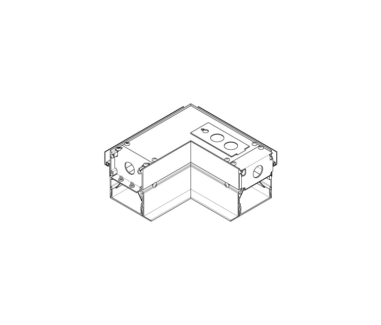
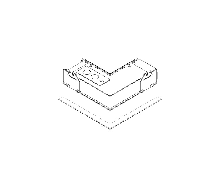
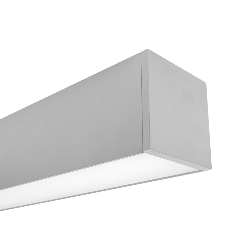
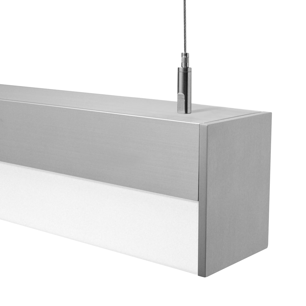
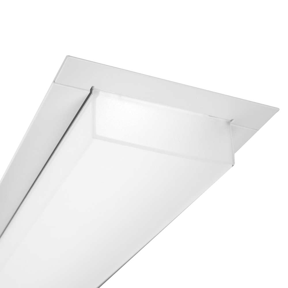
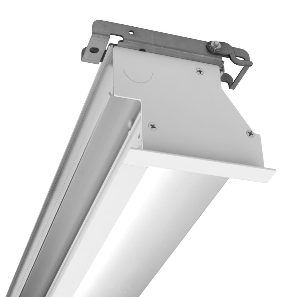
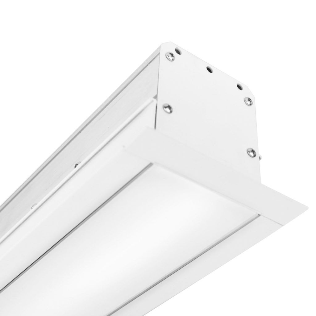
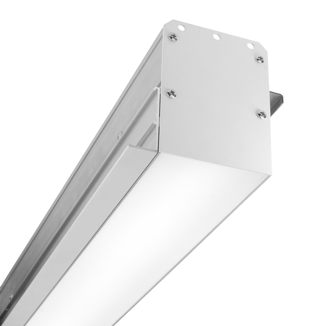
A member of the Wake series, the BSS430-P provides continuous linear lighting for perimeter applications. The 3” wide aperture luminaire is available for installation in common grid or hard ceilings with flange and trimless variants. In addition to straight lighting runs, inside and outside corner units are available at 90° and 135° angles.
For a corresponding surface, wall and cable mount fixture, see BSS214.
Available for QuickShip.
Specifications
Fixture housing and trim elements made of extruded aluminum and sheet steel and aluminum parts
Available for installation in typical 9/16” and 15/16” grid ceilings or drywall ceilings with flange and trimless options
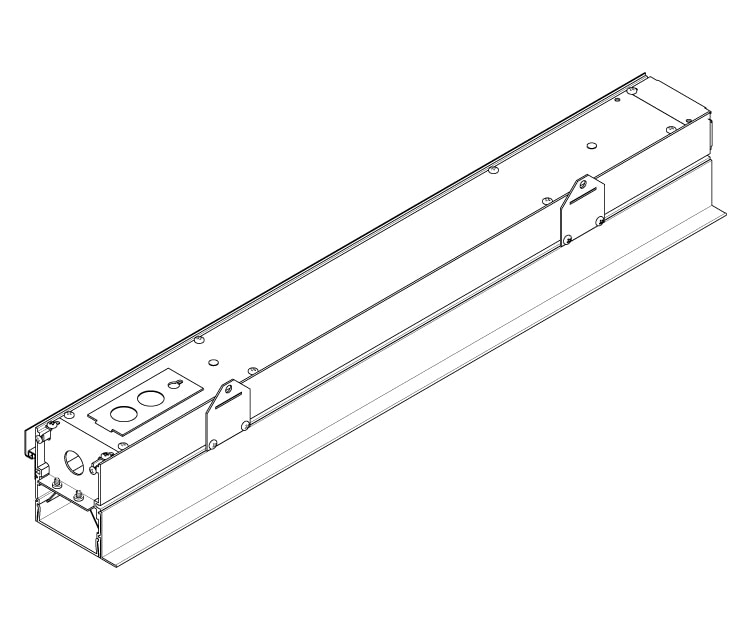
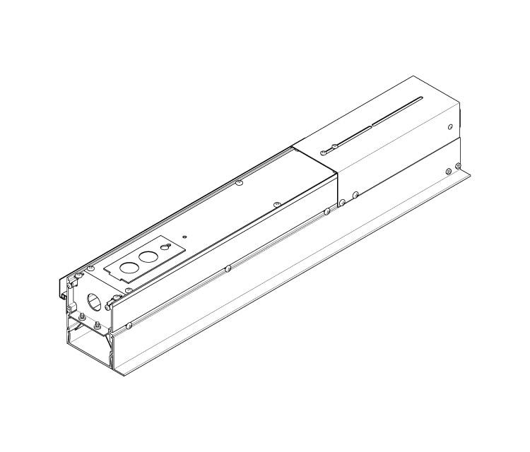
Fixtures available in straight lengths of nominal 2’–8’, 90° or 135° inside and outside corners and two field-trimmable filler units
Basic continuous run fixtures provided with 18 ga. wiring harness for 6 Amp maximum load (consult factory for runs requiring multiple circuits, etc.)
Available with Lambertian or wall graze optic options
Standard integral 120-277V driver offered with 0-10V dimming or non-dim (other dimming driver options available)
Integral 120-277V emergency battery backup available for 48” or 96” fixtures (supplied with remote test switch/indicator plate assembly)
Performance pending laboratory tests.
LEDs available in 2700K, 3000K, 3500K, and 4000K, within a 3 step MacAdam ellipse, all with 90+ CRI typical
Life: 50,000 hours L70
Chicago plenum rated option available
Nominal weight is 2.5 lbs. per foot
Limited five year warranty
UL and C-UL listed for dry and damp locations
IBEW manufactured and assembled
Made in U.S.A.
Product Data

Correlated Color Temperature
- 27: 2700K-90+ CRI
- 30: 3000K-90+ CRI
- 35: 3500K-90+ CRI
- 40: 4000K-90+ CRI
Driver
- ND: non-dimming
- D: 0-10V, 1%
- DTR: triac, 1%, (120V ONLY)
- DLV: electronic low voltage, 1%, (120V ONLY)
- HES: Lutron EcoSystem, soft-on/fade-to-black, 1%
- EL: eldoLED ECOdrive 0-10V, 1%
- ES: eldoLED SOLOdrive 0-10V, 0.1%
- ELD: eldoLED ECOdrive DALI, 1%
- ESD: eldoLED SOLOdrive DALI, 0.1%
Mounting
- T1: T-grid 9/16"
- T2: T-grid 15/16"
- FT: Flange trim
- TL: Trimless
- CF: consult factory for custom mounting
Run Configuration
Run configuration applicable to Straight and Filler Shapes. Corners are always adders.
- SN: single
- ST: starter
- AD: adder
- TR: terminator
Options
- CP: Chicago plenum (not available for F1 or F2 filler fixtures)
- ED: emergency driver (48” or 96" non-dim or 0-10V only)
- CF: consult factory for custom finish options
Shape
‡ Specify run length to the nearest 1". Factory will configure using the least quantity of fixtures as close to the desired run length as possible without exceeding the length. Run to be confirmed with a shop drawing.
- STR____‡: straight run (specify run from 2’–50’ to the nearest 1")
- F1: Filler 12-1/4” – 17-5/8”
- F2: Filler 23-1/4” – 28-5/8”
- CI90: corner inside – 90°
- CO90: corner outside – 90°
- CI135: corner inside – 135°
- CO135: corner outside – 135°
Mount Depth
- A: flush
- B: refer to table
- C: refer to table
Sections
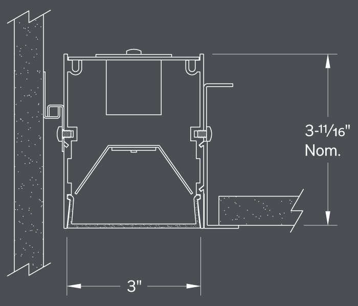
Shown with F1 optic, FT mount and A mount depth options
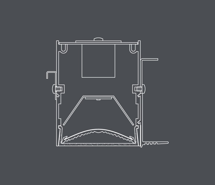
Shown with WG optic, TL mount and A mount depth options
Mounting Options
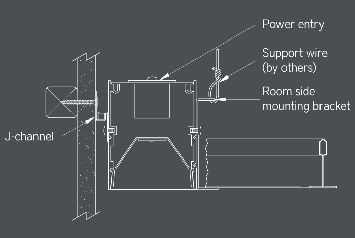
- Fixtures interface with common flat, regular and slotted t-grid types
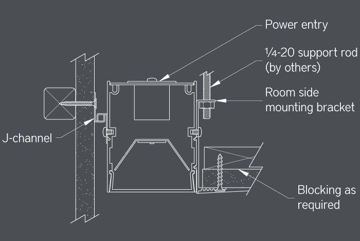
- Fixture hangs on provided heavy gauge j-channel, mounted to wall surface
- Housing additionally secured with support wires or ¼-20 threaded rod (by others)
Ordering Code: T1 and T2
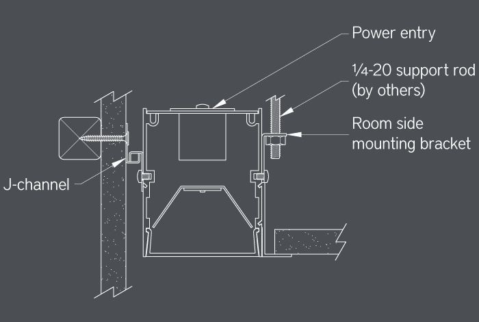
- Installs before 1/2” or 5/8” drywall
- 3/4” wide extruded aluminum trim flange in matte white finish
- Fixture hangs on provided heavy gauge j-channel, mounted to wall surface
- Housing additionally secured with ¼-20 threaded rod (by others)
Ordering Code: FT
- Installs before 1/2” or 5/8” drywall
- Fixture hangs on provided heavy gauge j-channel, mounted to wall surface
- Housing additionally secured with support wires or ¼-20 threaded rod and self-tapping drywall screws (by others) into blocking as required
Ordering Code: TL
Shape
Layout Example
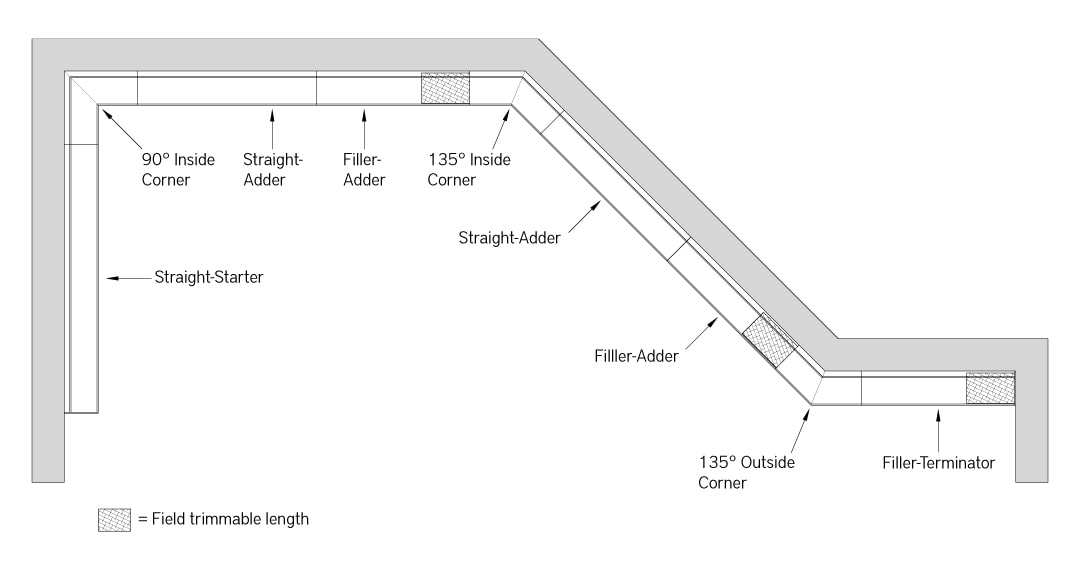
After installing mounting channels around the perimeter, install the corner fixtures, followed by straight fixtures. Trim the filler fixtures to fit remaining run lengths and place onto the mounting channel.
IMPORTANT: Provide fixture layout with run lengths to Bartco Lighting. Factory will determine the optimal individual Straight, Filler and Corner fixtures for the layout.

